Computer Controlled Cutting
Table of content:
1 - Group assignment1.1 - dots 1.2 - cut
2 - Individual assignment
2.1 - Vinyl cutting
2.1.1 - design 2.1.2 - setting the machine 2.1.3 - generating toolpath 2.1.4 - worst experience
2.2 - Laser cutting
2.2.1 - Design | Jigsaw puzzle 2.2.2 - Generate toolpath | Jigsaw puzzle 2.2.3 - Results | Jigsaw puzzle 2.2.4 - Design | Construction Kit 2.2.5 - Results | Construction kit
Group assignment
the group assignment was for laser cutting
in the group assignment we were told to find out Focus, Speed, Power required for different material and find out kerf after the material is
cut.
a brief explaination about kerf:
in the laser cutting machine, the materials are cut with the laser beam. This laser beam burns the
material as it passes, however due to compressor, the material won't catch fire. In the process of cutting, there is loss of material and
that will reflect in the actual dimensions. For example, you designed a square with 5mmx5mm dimension and cut that square in laser cutting
machine. Now the acutual dimension of the square won't be 5mmx5mm, because of loss of material in the process of cutting or sometimes due
to inacuracy in movement of laser header. Let's assume you got the dimension 4.6mmx4.6mm whenyou measured the square. That 0.4mm is the kerf.
And so next time when you want your piece with 5mmx5mm dimension,you will add kerf to the dimension so you will give 5.4mmx5.4mm dimension
while designing.
i guess the reason behind the group assignment is to first get your hands-on the laser cutting machine/ get to know how the machine works. the
group assignment was divided in 3 teams and the teams were assigned different material to work on. Me and Jaydeep were assigned to work on
cardboard/corrugated sheet. In the laser cutting machine there are different processing mode/ different ways you can use laser cutting machine
like cutting, engraving, dots and pen
Between me and Jyaydeep, I was working on cutting and dots.
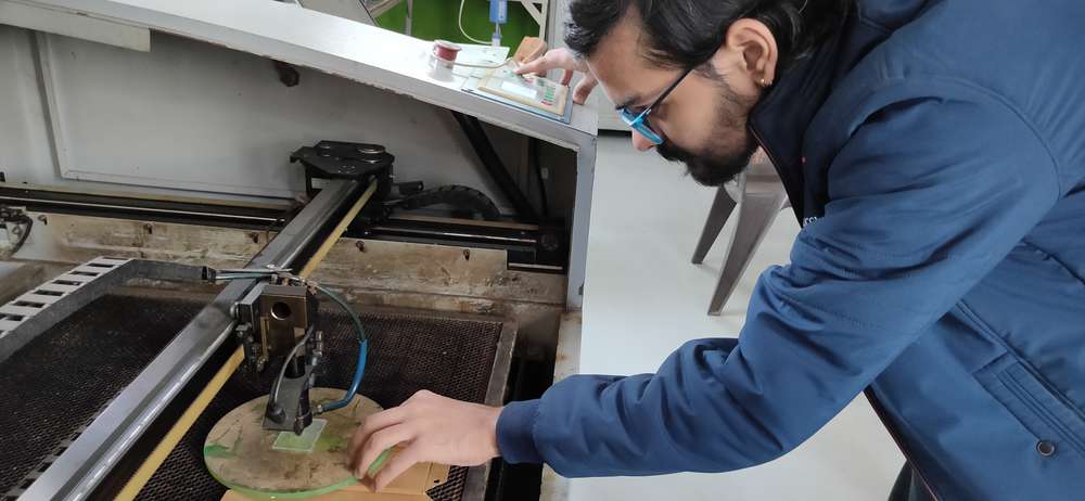
a brief description about the machine:
In the lab we have SIL CO2 laser cutting machine with which we can cut cardboard, plywood, MDF, acralyic or any soft material. We cannot cut
any hard material. It will be a bad idea to use any reflective material, no matter how hard or soft it is, it wil be hazardous if the laser is
reflected anywhere else than the material you want to cut.

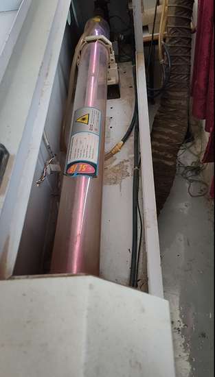
There is 3 concentric tubes inside the laser cutting machine. In the inner most tube, With the help of electricity and CO2, laser is generated
and on both end of the tube there is reflective mirrors. After the laser bean is generated, it will contunuously bounce on both the mirrors
and at one point, it will reach the nozzle/header with the help of 3 mirrors set at 45° angle,
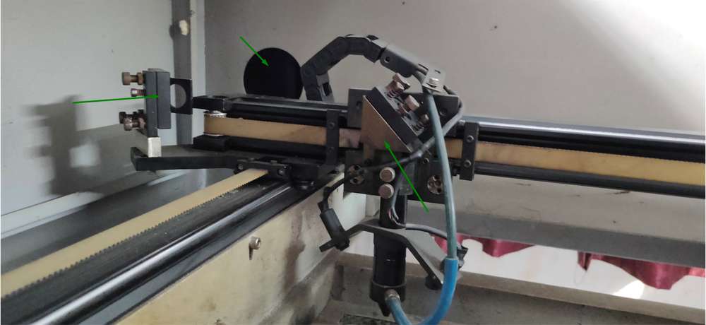
inside the nozzle/header, there is a concave lens that focuses the laser upto a dot.
outside the innermost tube, there is a second tube insie which water is constantly running with the help of cooler(CW-5200) to cool down the
laser tube. And the third tube is a protective cover.
You can operate the machine with these buttons,
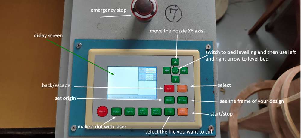
i haven't used the rest of the buttons, will probably update once i use them.
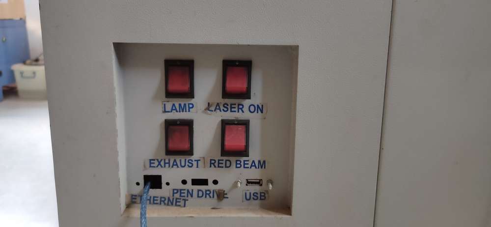
before you start cutting make sure these three things are turned on,
COOLER. We were told to check the temperature of the cooler and that it must be below 30°
COMPRESSOR. If the compressor is off, the material you want to cut will start to ignite
EXHAUST. exhaust helps extracting the smoke out of the machine so make sure it is on.
TURN OFF THE LASER. The laser won't start unless you press the start button, however it is a great habbit to always turn the laser off whenever
you open the lid, either to remove or insert the material.
apart from this, try your best to remain alive in one piece.
We were using 3mm cardboard. Regardless of the material you are using, height between the header/nozzle and the material should be 8mm in our
machine's case. The height varies from machine to machine though. You need to adjust the bed level by placing something between nozzle and
the material, and it should be 8mm thick.
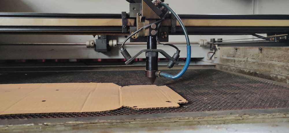
So the focus will be8mm.
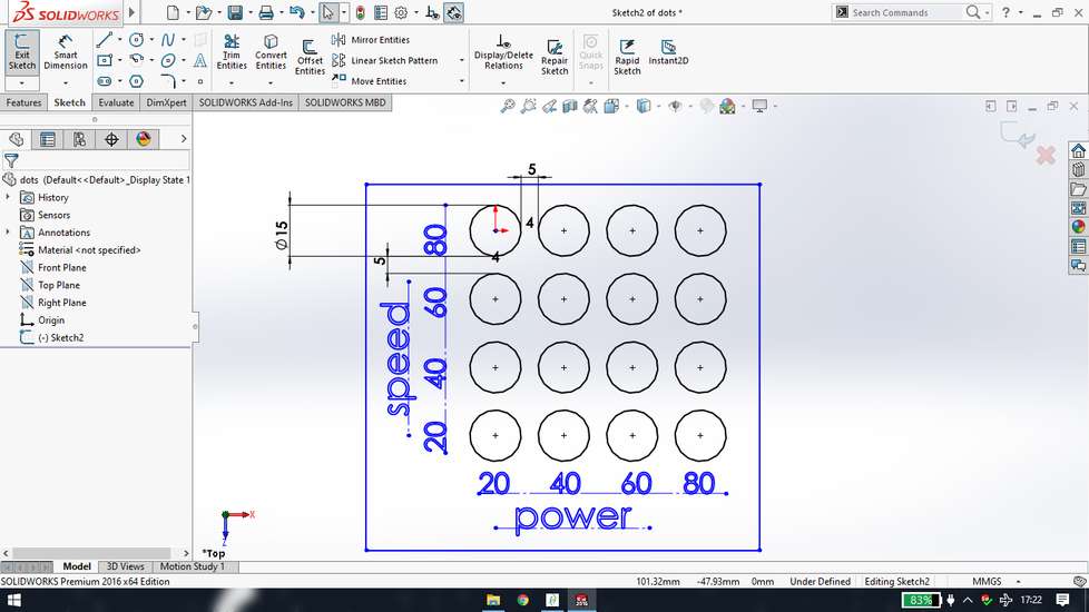
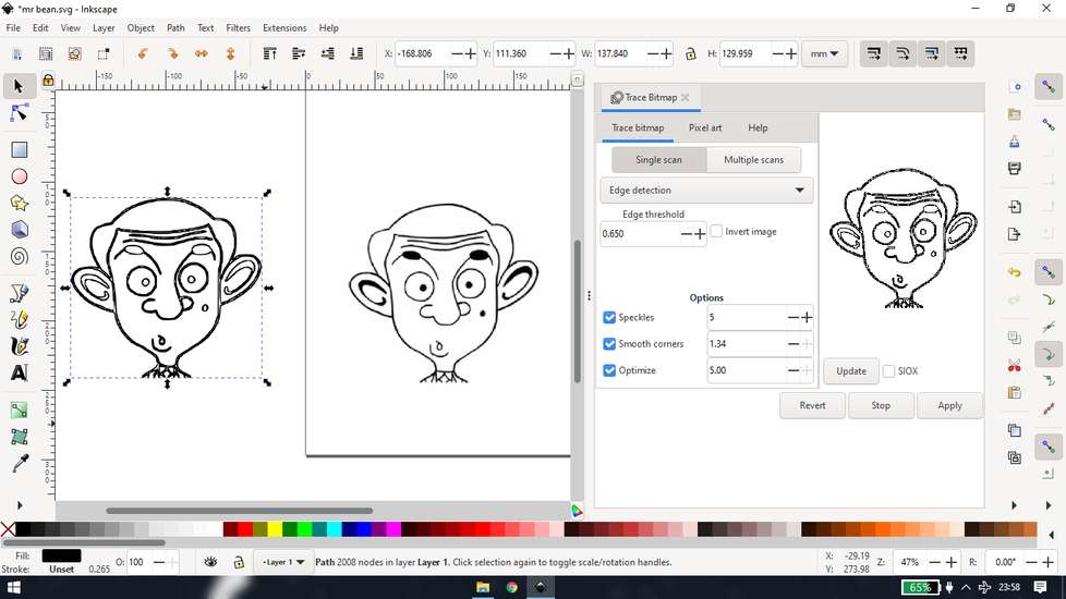
<<<---DOTS--->>>
Now before designing making pattern with dots, I decided first see how
will the cardboard react with different speed and power for dots mode. I took the reference of this and designed a file
(https://www.instructables.com/Test-your-material-to-determine-laser-speed-and-po/)
You can use any software to design your model, just make sure there is option to export your file in .dxf format. It is good practice to
save the original file of your model alongwith the .dxf file, just in case you need to make changes later.
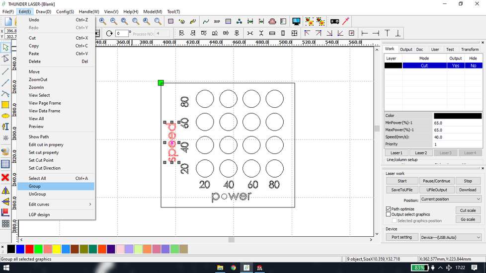
For laser cutting, I am using RDWorks software. So open the .dxf file with RDWorks. rdworks will automatically ungroup every shape in your
model, so you can group them from edit>group
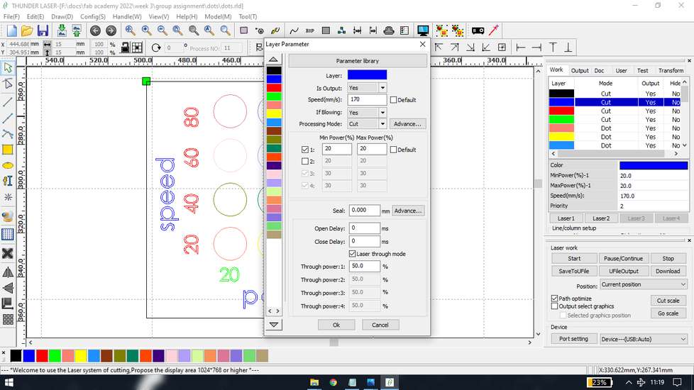
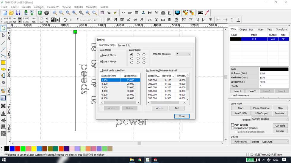
In rdworks, you can also assign different speed and power to different shapes by assigning them a unique color. So select a shape, assign
the shape a color, double click on the color that appear on the tool box on right side and assign that color power, speed and the processing
mode.
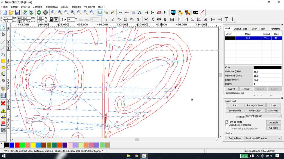
This was the result
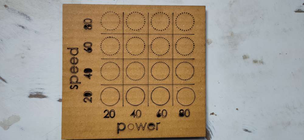
Even with 20% power and 80 ms speed the laser went through and all the holes were cut nicely. So obviuosly the speed below 80ms and power
above 20% will have nicely cut holes. therefore i wanted to see how high can i set the speed with 20% power to cut the holes. So i designed
the another file and printed them with 20% power and diferent speed I also set different dot intervals.
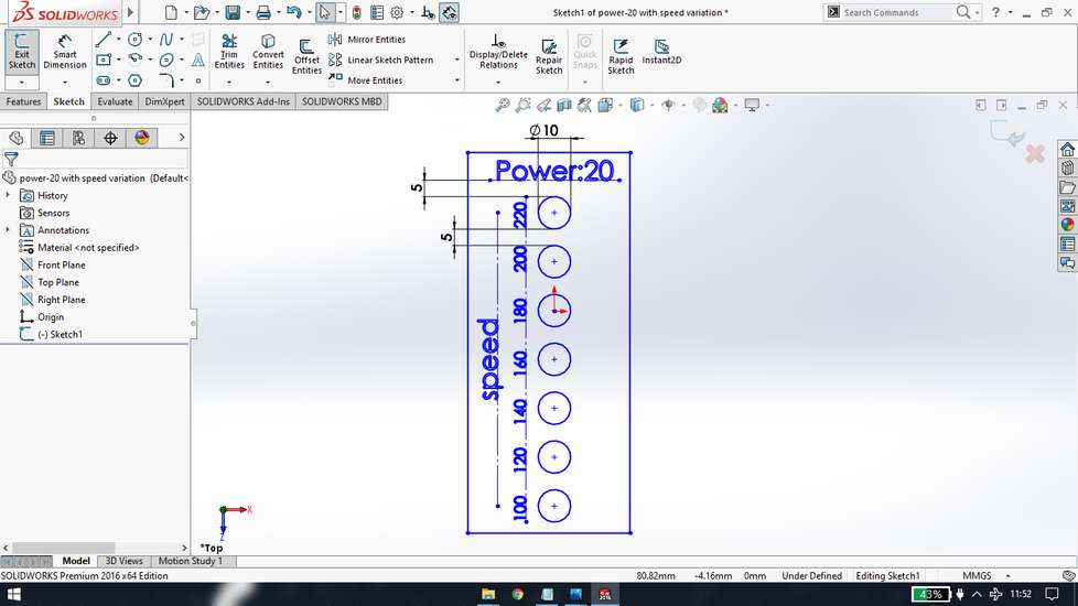
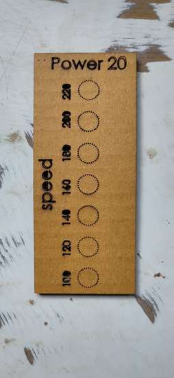
it was concluded that with 20% power, you can set speed upto 220 ms and will get fine holes
To test if the parameters will work in large files i,
downloaded a file and traced the edge in the inkscape. You have to play with the settings to get better tracing. Again save the original
file and export another file as .dxf format
I cleaned the drawing by removing unwanted shapes from rdworks and assigned the color for cutting and dots and set the parameters accordingly.
I used 200ms speed for safety.
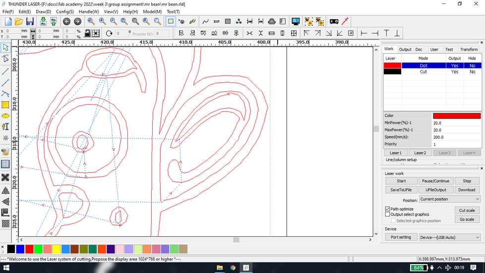
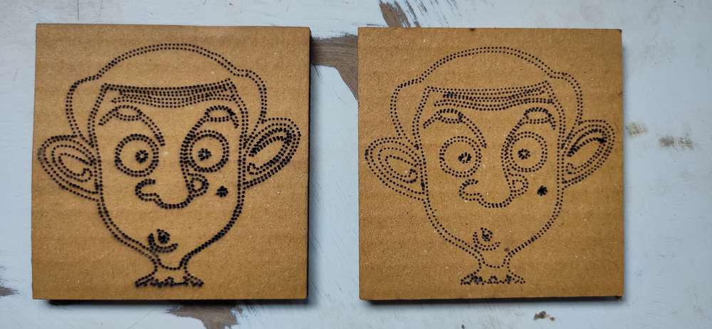
for some reason, the top of the cardboard had some burnmarks while the bottom one was clean, so i mirrored the drawing and cut it again and
here are the results
(you can mirror the drawing from draw>horz mirror/vert mirror)
if for some reason the alignment in your rdworks and the alignment in the laser cutting machine(preview in the screen or the result after
the cutting is done) is different(mirrored, specifically) have these option checked from config>system settings
<<<---CUT--->>>
i used the same principle from the dots for defining parameter for cutting
designed the file

exported them as .dxf file and in the rdworks assigned different speed to different color that were assigned to different shapes
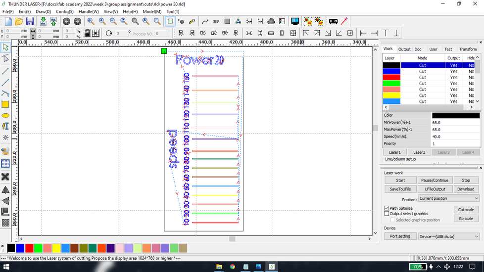
here are the results
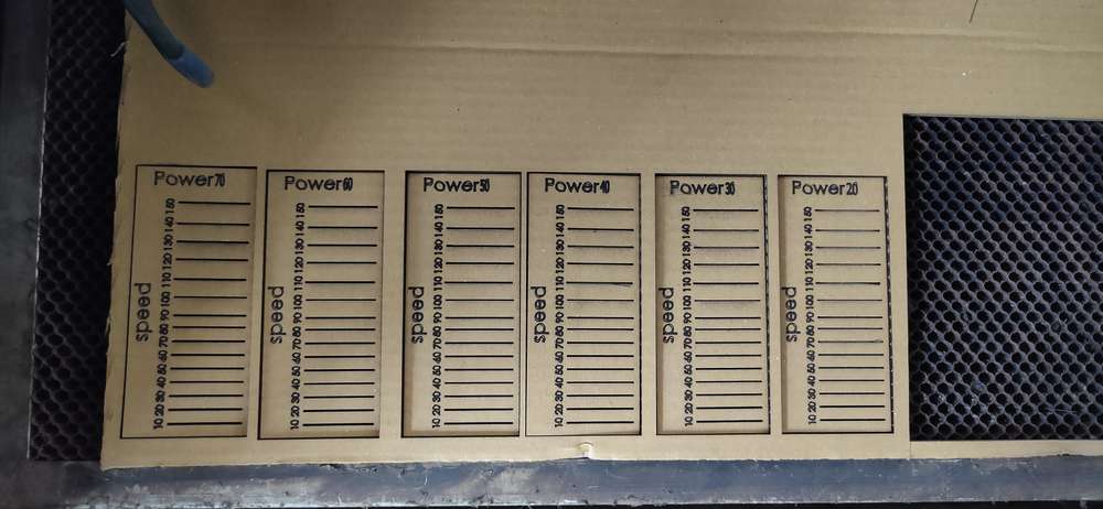
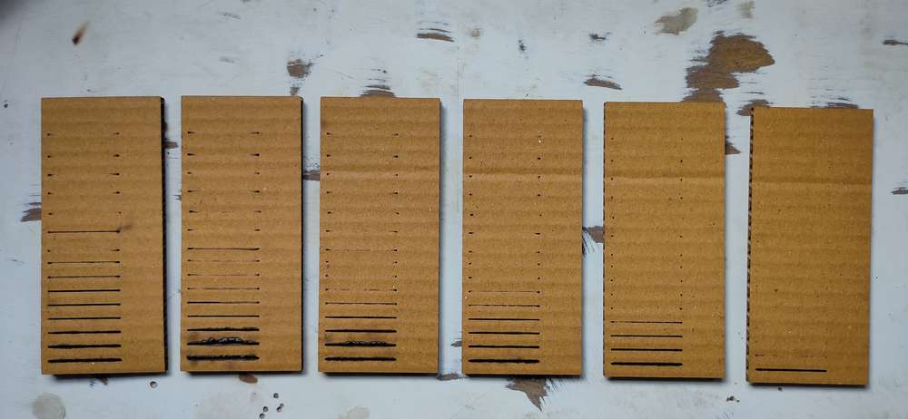
it can be concluded that, if you want to cut with 50ms speed, you'll need to give 70% power. If you want to cut with 40ms you'll need 50% power.
You can use 40% power but you will need to push the piece
About kerfz`,
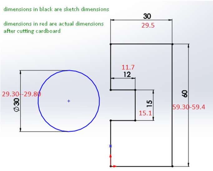
You will find the kerf value of different material with different speed and power in our group assignment.
reference link: https://www.thingiverse.com/thing:4575909/files
rd works link : https://rdworks.software.informer.com/8.0/
you can see the work of other students on the group assignment here:
https://fabacademy.org/2022/labs/vigyanashram/groupassig/groupassignment1.html
Individual assignments
in the individual assignment we were suppose to design and cut something in vinyl cutter
Vinyl Cutting
just like any CNC machine(computer numerical control machine) you'll need a CAD(computer aided design) software and you'll need a CAM(computer aided machining/manufacturing) software in order to fabricate your design. In the CAD software, you design your model and in the CAM software you convert the CAD file into a format or a toolpath that the machine understands. There are certain software where you can generate the CAD and CAM file from a single software.for designing i was using fusion 360. Fusion doens't export the file in svg or png format. So i had to export file in dxf format and open that dxf file with inkscape, modify it and export that in svg or png format. And to generate toolpath i was using installed mods project in linux. so in this case i had to use 2 CAD software- fusion and inkscape and 1 CAM software- mods project.
Design
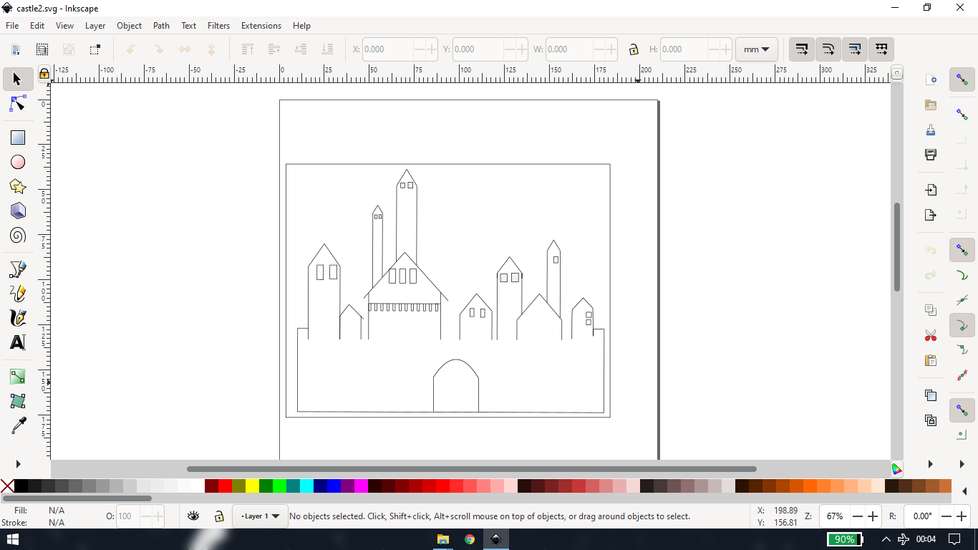
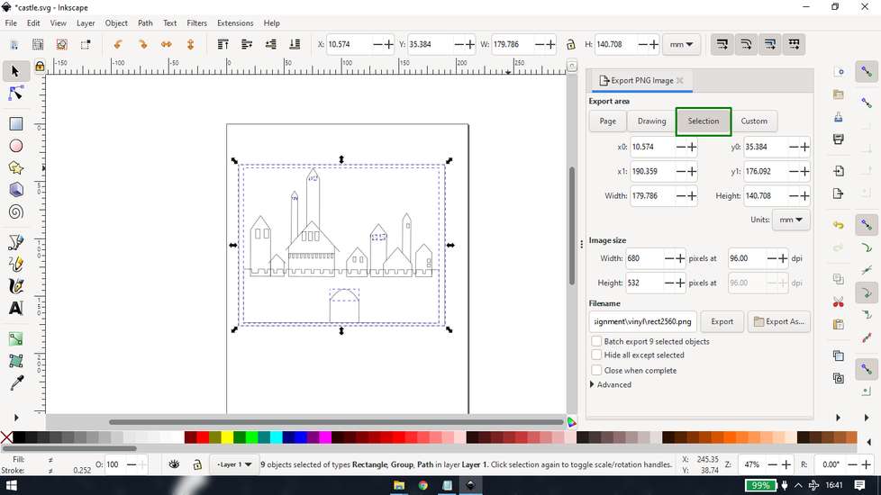
I designed a castle in fusion 360
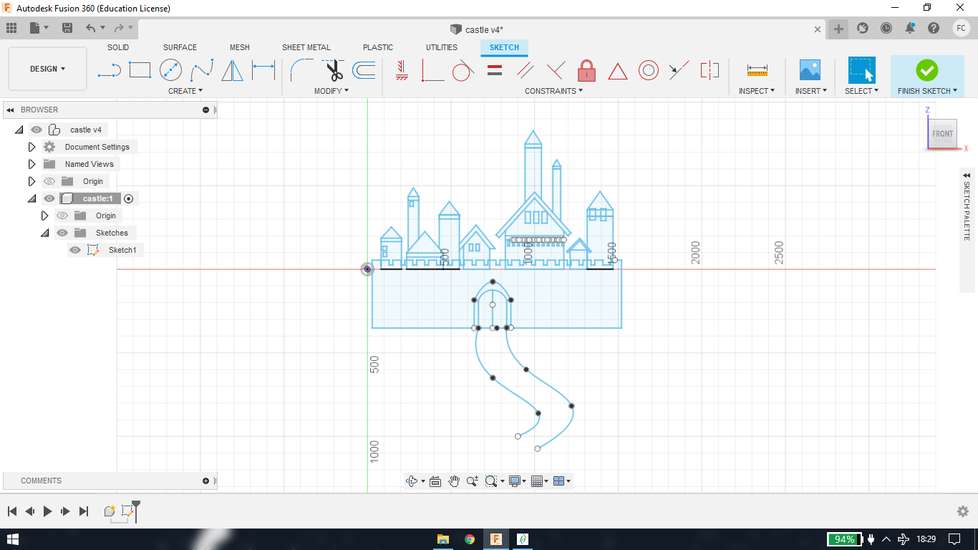
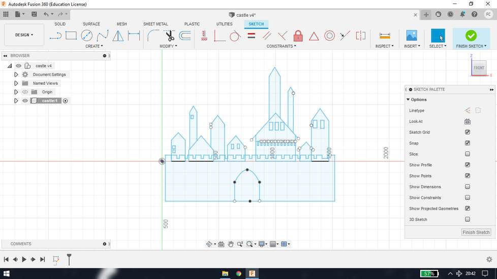
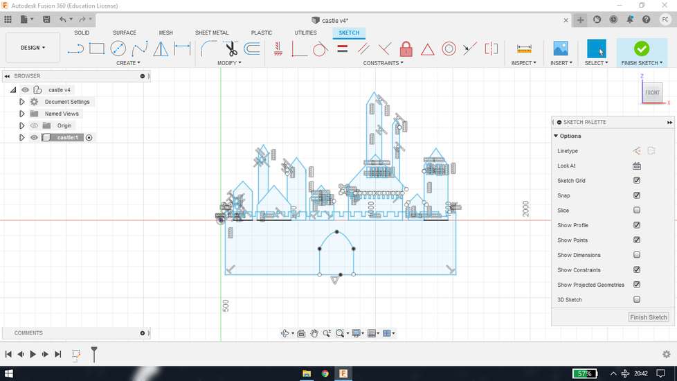
then i realised that the vinly cutter is going to cut every line and no draw it, so tried to simply it
(haven't traced any image)
i then exported the file as .dxf file and opened in inkscape

i increased the width of the line from fill and stroke menu, Object>fill and stroke
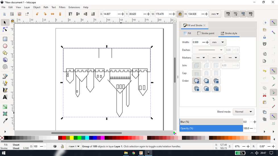
i then again simplified a bit more and gave it a border to easily peel the content off
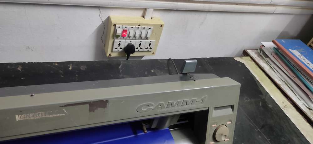
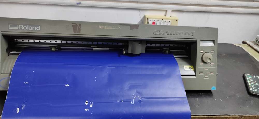
Setting the machine
>
before loading the vinyl roll into the machine, do confirm that,
the roller of the machine should be under white strip, or else the machine will show some error
the hinge should be unlocked, or else you won't be able to load the vinyl roll
after loading the vinyl rolll, lock the hinge so that the vinyl won't slip
select the type- roll means full vinyl roll, piece means just a piece of vinyl. If you select the piece, the machine will calculate the
length and width of the paper, and will show error if the size of print/cut is large than the piece of paper. I have tried it but forgot to
document, may be next time.
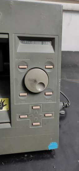
set the origin
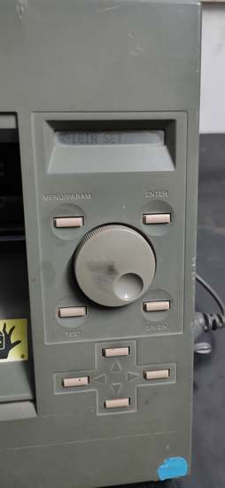
after the origin is set, the the range of cutting will be the point of origin to where the left roller is set.
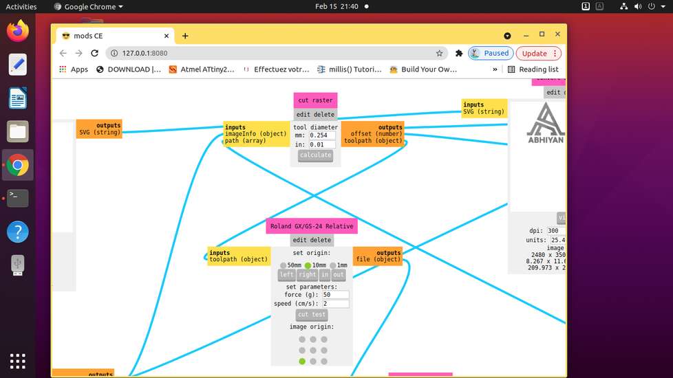
Generate toolpath
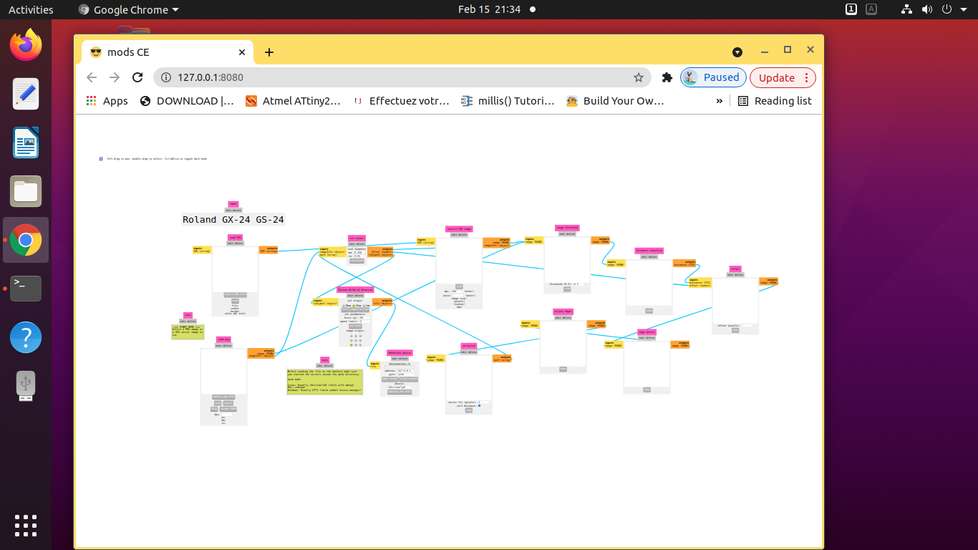
we were using a software called mods project, just like python that uses internet browser as a local host, i don't know the term for that.
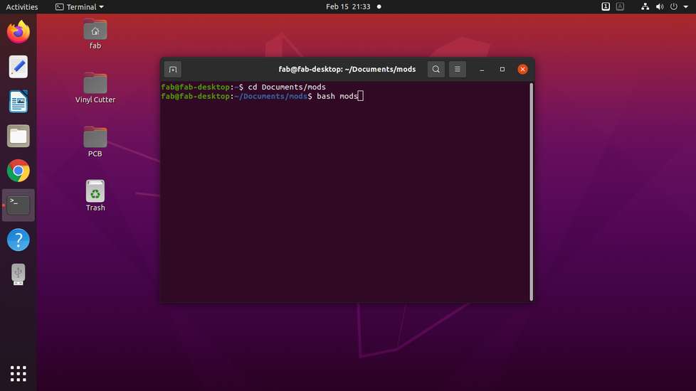
in the terminal, run these commands
cd Documents/mods
to set the directory where the mods project is installed.
bash mods
to open the software in you browser as local host
right click and select programs>open program>cut(under your machine name)
the interface will look something like this
if you have svg file, upload the file under svg tab
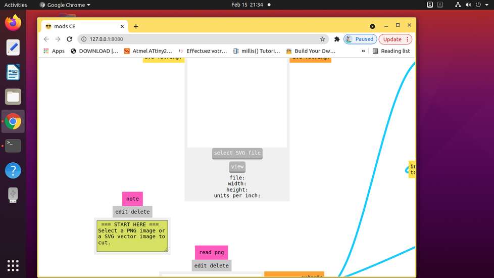
if you have png file, upload the file under png tab
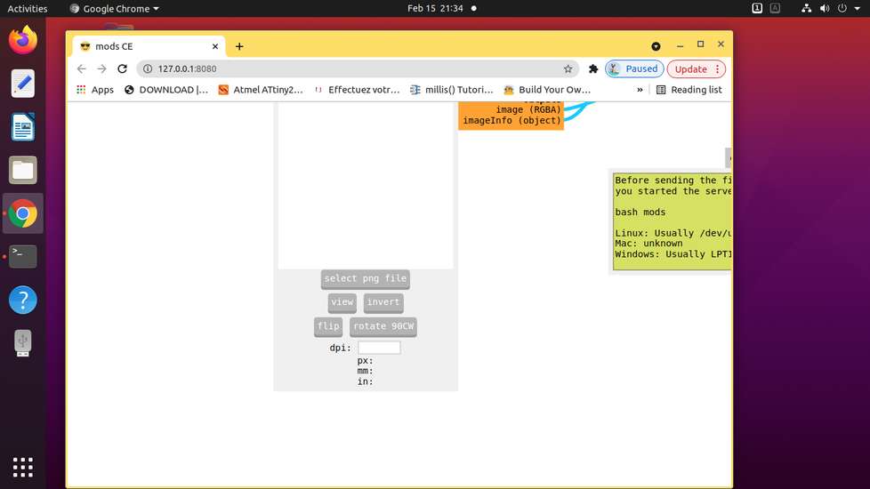
after setting the speed and force hit calculate
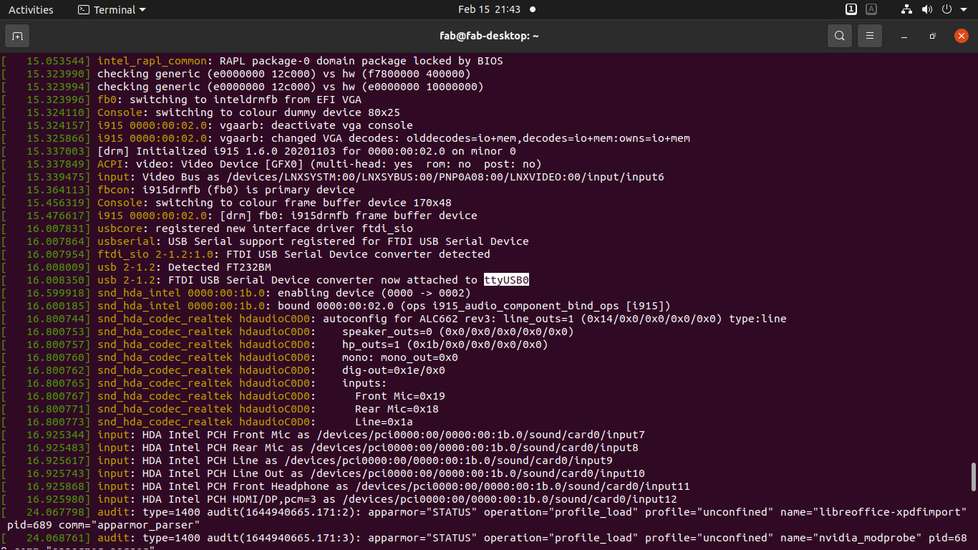
enter the name of your USB port in this format: /dev/"devicename"
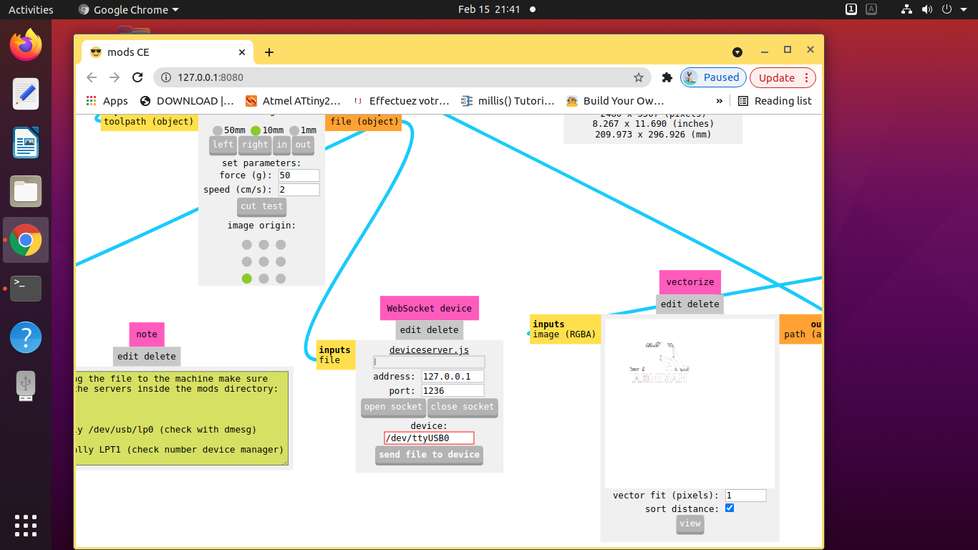
you can find name of the USB port by running dmesg code in terminal. I wasn't able to run dmesg command after running the bash mods command,
to it is recommended to find the name of the usb port before opening the software
what went good with vinyl cutting
that using the vinyl cutter is finally over and i don't need to use the vinyl cutter for some time. At least not as a complete noob.
what went bad with vinyl cutting
everything
[1] mistake in design
it took me a couple hourse to design that castle, and in the midway i realised that the machine is going to cut everything that is in the file
and so i had to make some changes there were a couple of glossy vinyl roll, which wasn't giving me good results. For some reason, the machine
was double tracing the design and that too only in glossy vinyl. So i would cut the design with same file and use different vinyl and will get different result
photo of red vinyl i was't able to capture the double tracing situation.
[2] when printing with the svg file, the header(with blade) would move a couple centimeter to the left and then start cutting.
i tried to move the design in one corner of the page, but it was still leaving a lot of space/margin

i then tried to export the design as png format with selection tool and then it was printing right where i set the origin. Do not forget to
select everything you want to cut
[3] after the design was cut
even after tweaking the force and speed, it wa difficult to peel off the extra vinyl off without accidentally peeling the main design.

SO i had to manually trace each and every line with a pen knife and because of that, the back side of vinylwould tear.
[4] after the design was peeled off
after patiently peeling the unwanted vinyl off the roll, and sticking the main designonto a masking tape, it turned out that the vinyl isn't
very good with sticking onto a cardboard. so if i stick the masking tape onto cardboard (with the vinyl already stuck to the masking tape),
press the masking tape so that the vinyl would stuck onto the cardboard and then finally peel the masking tape off, in the hope that vinyl
would have stuck onto the cardbaord, the vinly just won't stuck onto cardboard. So i had to patiently peel the masking tape off while manually
press every quarter inch of vinyl onto cardboard. Here are the results

Laser Cutting
in the individual assignment, we were suppose to design and laser cut parametric construction kit which can be assemble in
multiple ways
Design | Jigsaw puzzle
i focused more on parametric design and ignored the construction kit by using different type of joints. I thought i'll design something so
that the vinyl cutting and laser cutting can be shown on the same thing and so I dsigned jigsaw puzzle pieces
a brief explaination about parametric design:
let's assume that you have 10 different models and you want to make holes of equal dimensions in them. Now instead of giving them dimensions
in number, like 10mm, you can give a name, for example "hole". Now assign that name a number, for example 10mm. You might be thinking why the
extra process of assigning name and not directly giving dimensions number, but suppose you printed/cut the design and the hole is a bit too
big. So if you have assigned the dimension a name, all you need to do is change the dimensions/value of the said name. For example, from Hole=
10mm to Hole=9mm and dimensions of all the 10 holes will change. If you had assigned number as dimensions, you will need to change dimensions
of all the hole one by one. So this process of changing value of one thing due to whcih value of multiple things changes automatically is
called parametric design. You will understand it more clearly if you read description under laser cutting.
for laser cuting i was using fusion 360 for designing and RDWorks to generate toolpath. So i design a sketch/model in fusion, export it in dxf
format and open that with RDWorks to assign your design a color and the color represent speed, power and processing mode. I have explained the
RDWorks software in more detain under the group assignment uunder this week.
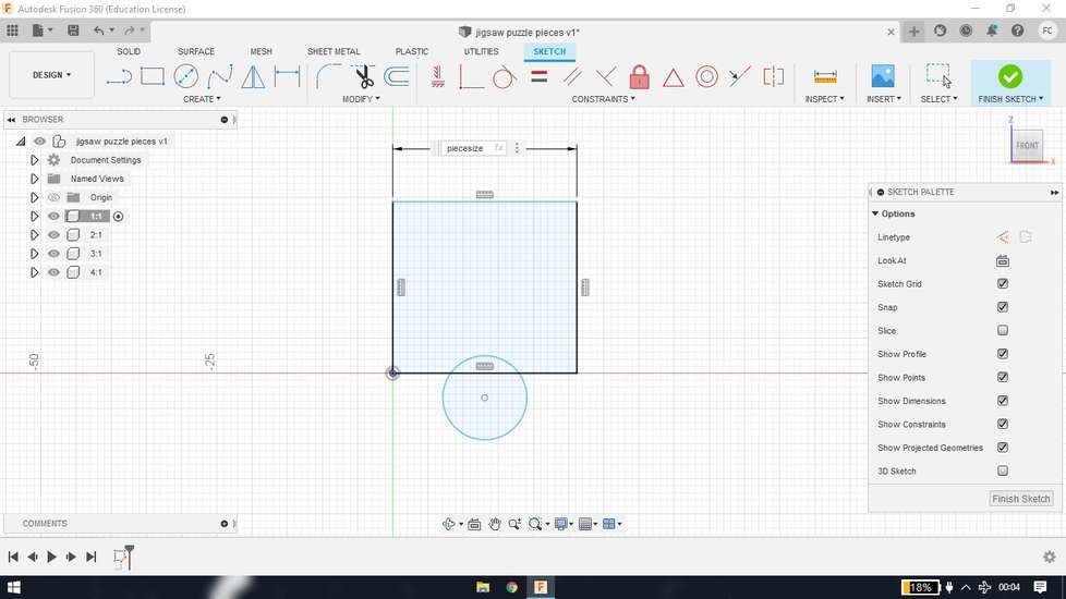
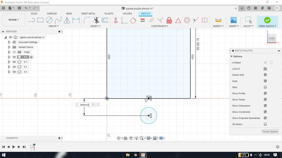
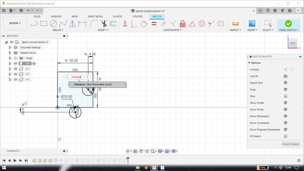
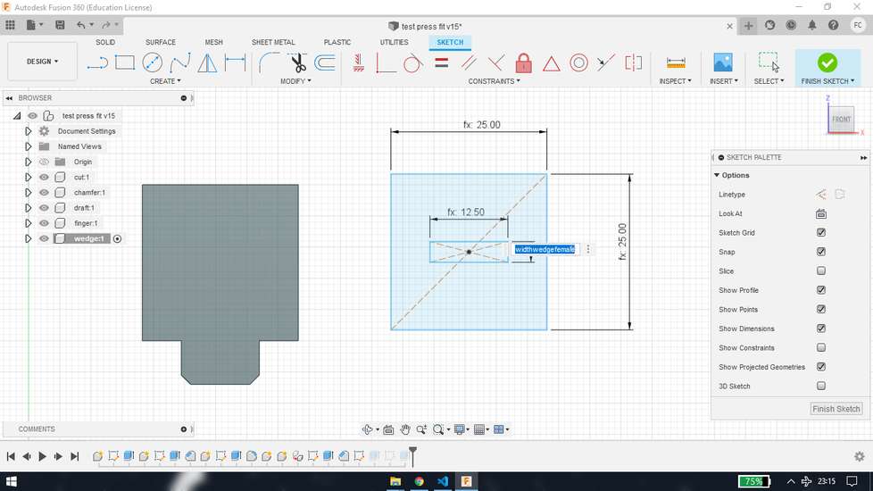
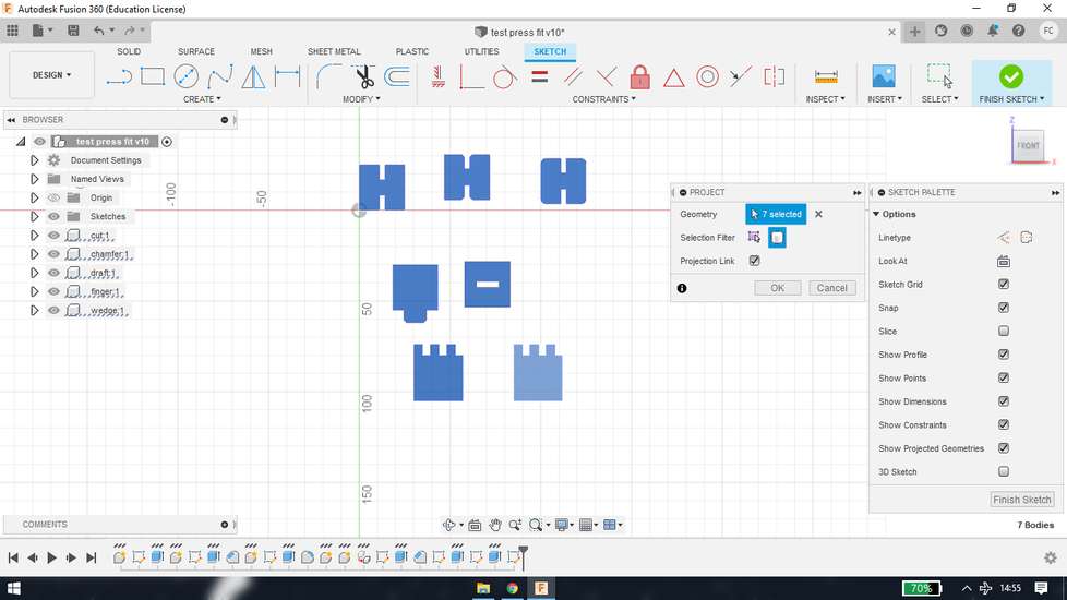
I designed the pieces in fusion
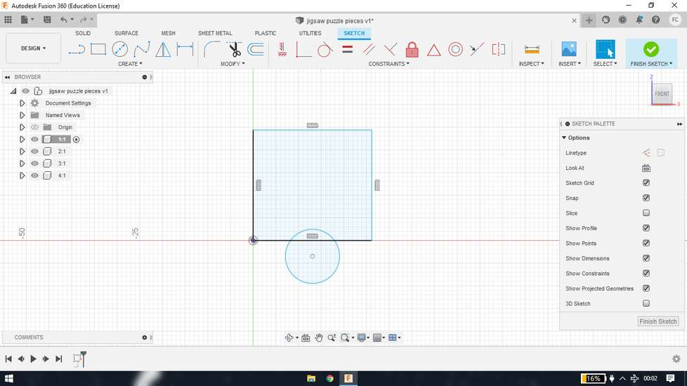
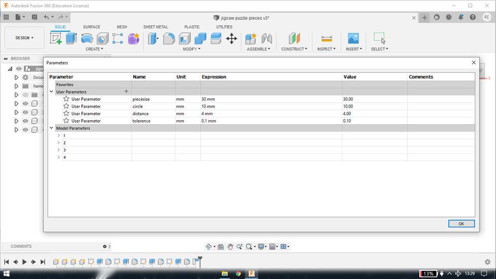
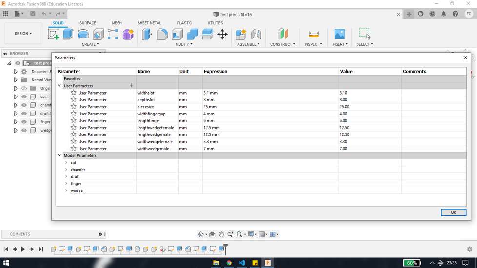
i set the parameters for the size of piece, size of circle, distance between the circle and square and tolerance/kerf. The image below of the
parameters table is the final one after making some changes
i then applied that parameters into the design
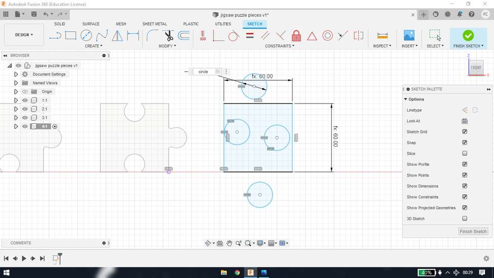
so after i laser cut the pieces, if the piece are loose or tight,i just need to make changes in the parametric table. For example, after
cutting the piece,if the pieces are loose when aligned, i would know that the size of circle is okay, i just need to tweak the distance and
tolerance/kerf values.
Generate toolpath | Jigsaw puzzle
i then exported the design as .dxf format and with the rdworks software i uploaded the design in the laser cutter machine. To upload the design
in the laser cutter machine, connect your system wth the laser cutting machine via USB cable and hit the download button under the
"laser work" tab

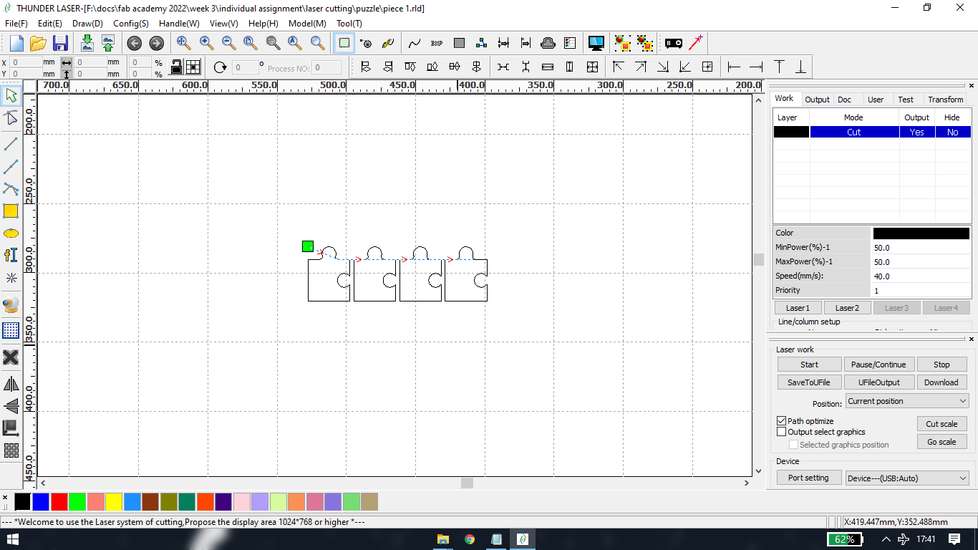
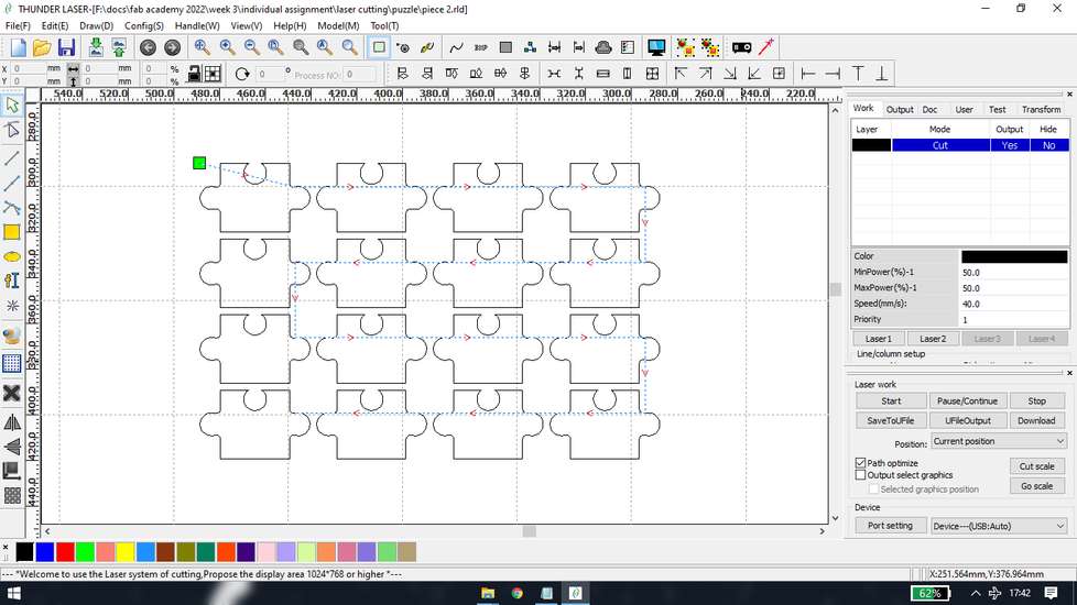
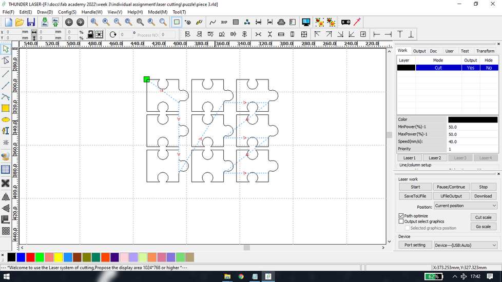
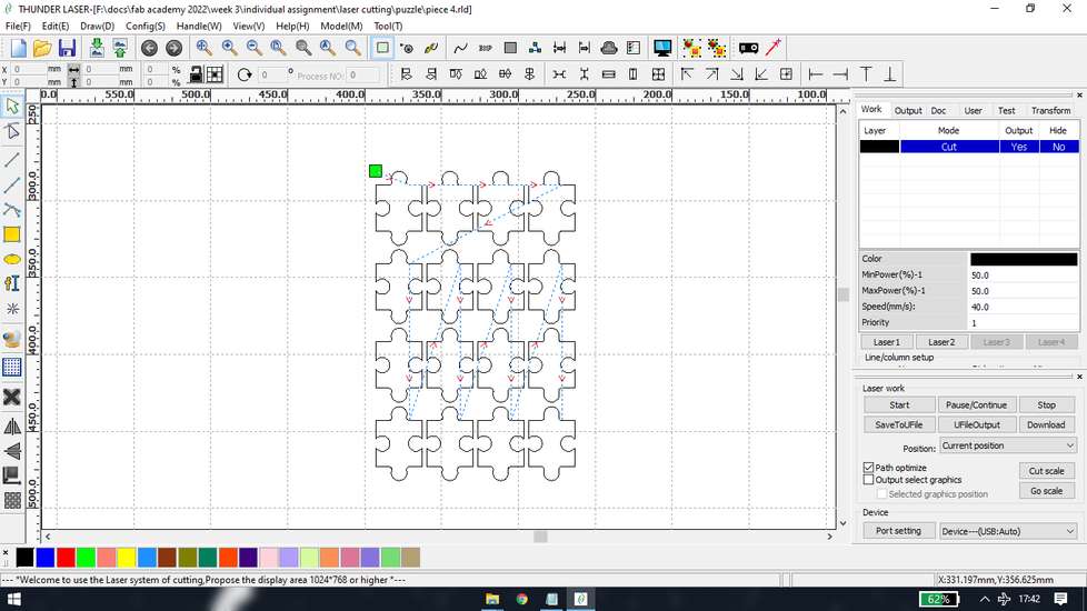
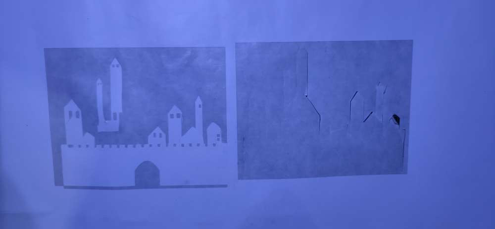
Results | Jigsaw puzzle
here is the result after cutitng the cardboard pieces

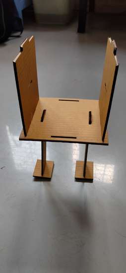
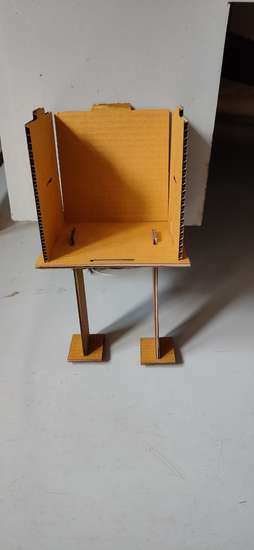
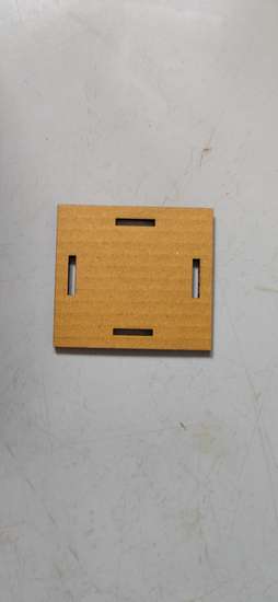
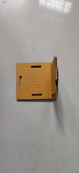
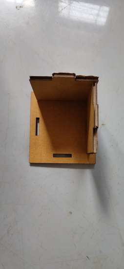
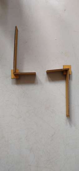
Design | Construction Kit
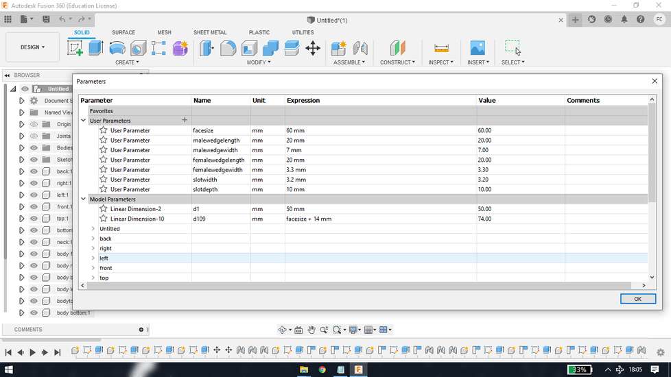
Then i wanted to explore different type of joints, so i again designed them in fusion with the help of parametric design
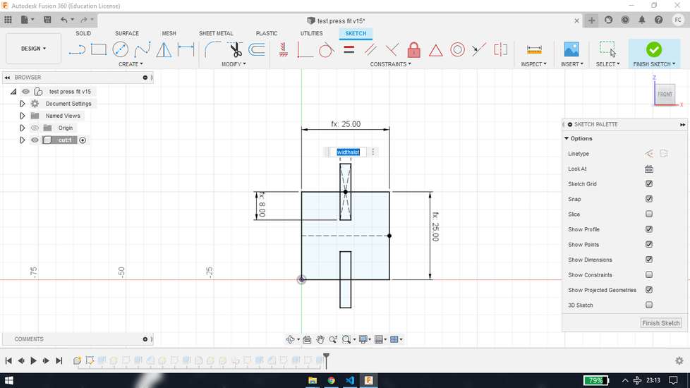
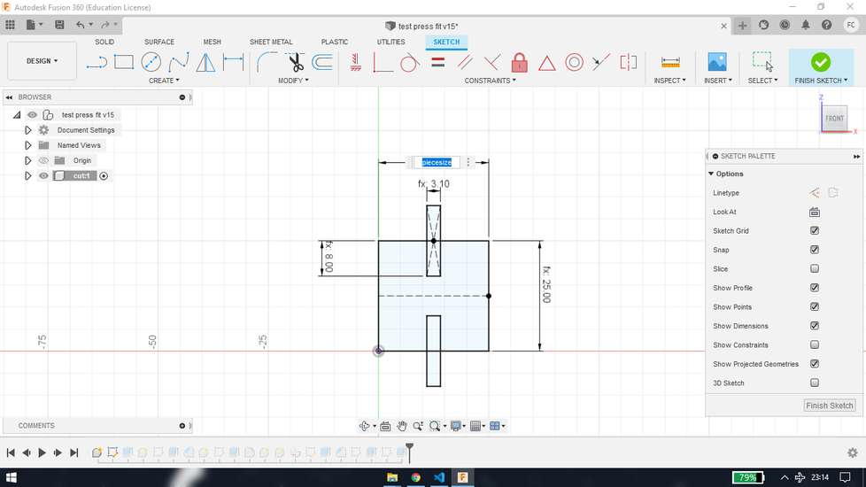
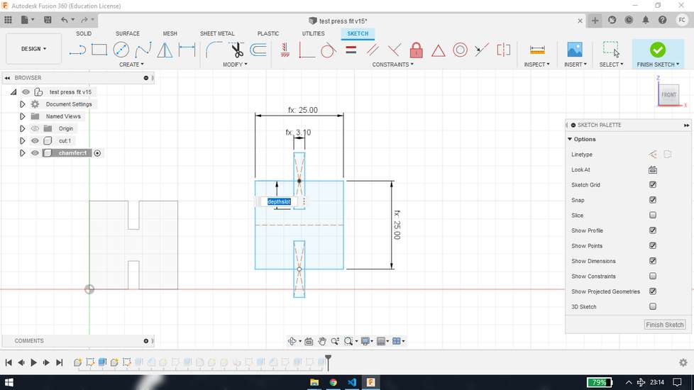
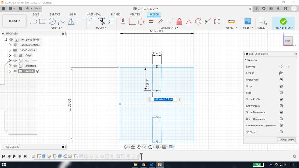


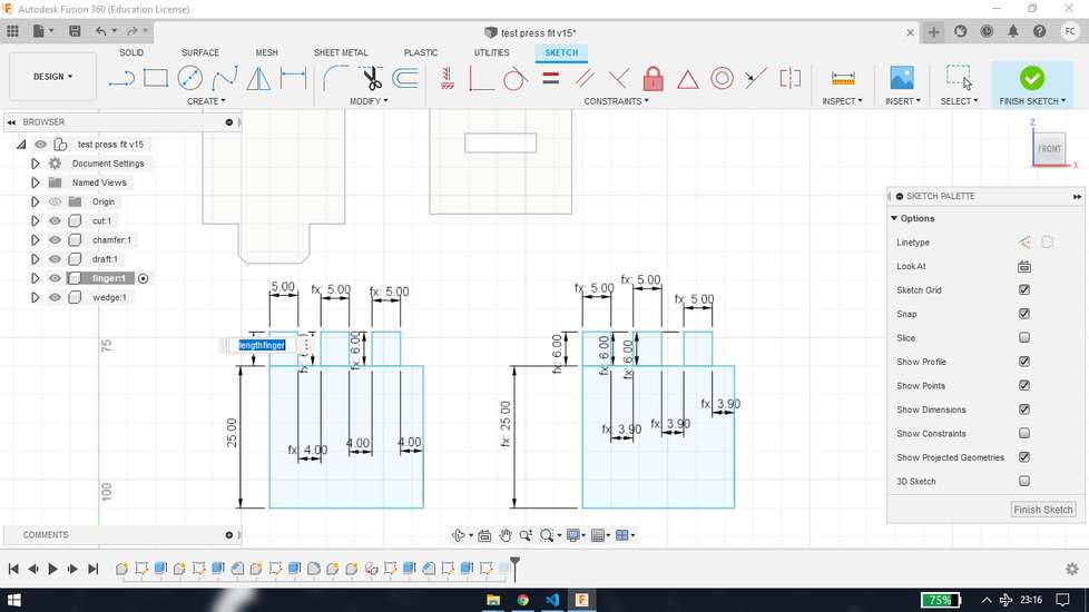

here is the parametric table
so if i try the joint and it is loose or tight, i just need to change the width and depth of the slots.
How did i get the slot width dimension 3.1?
With the help of vernier caliper i measured the tickness of cardboard sheet it gave me an approximate dimension of 3.6mm. Now i did worked on
measuring the kerf value, however i didn't applied the kerf principle because in kerf, you have to add dimensions but it will result into
loose fit of the pieces so you need to add a certain amount of dimension for kerf and you reduce the dimensions to get snug fit pieces.
Instead i made sketch with multiple dimensions like 3.6mm+0.1mm, 3.6mm+0.2mm, 3.6mm+0.3mm - 3.6mm-0.1mm, 3.6mm-0.2mm, 3.6mm-0.3mm and conerted
them into dxf file,
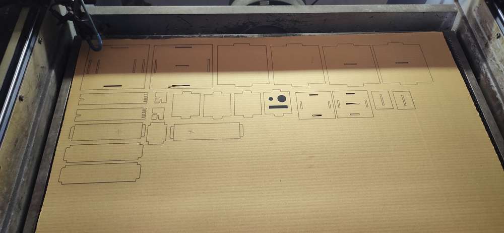
after cutting the pieces, it was concluded that i cannot use any dimensions above 3.3mm for the slot width. So i again printed few pieces and
the 3.1mm slot width was giving better result in terms of snug fitting.
exporting the design in dxf format from fusion is a bit tricky,
select a plane where all the pieces are covered, and with the help of project feature selectall the bodies. Shortcut key for project
feature is "p"
on the left hand side,under the sketches folder select the sketch that you just created,right click and select save as/ export as dxf file.
If you directly export dxf from the "export", you'll see a black design in your dxf file
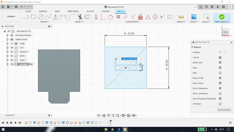
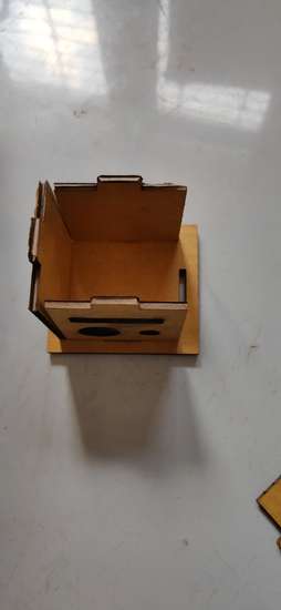
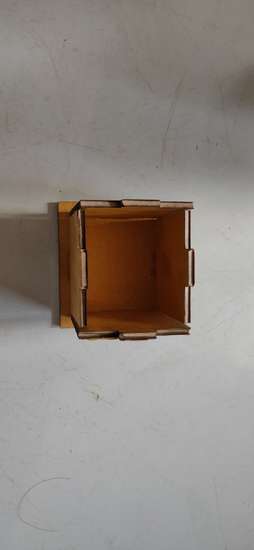
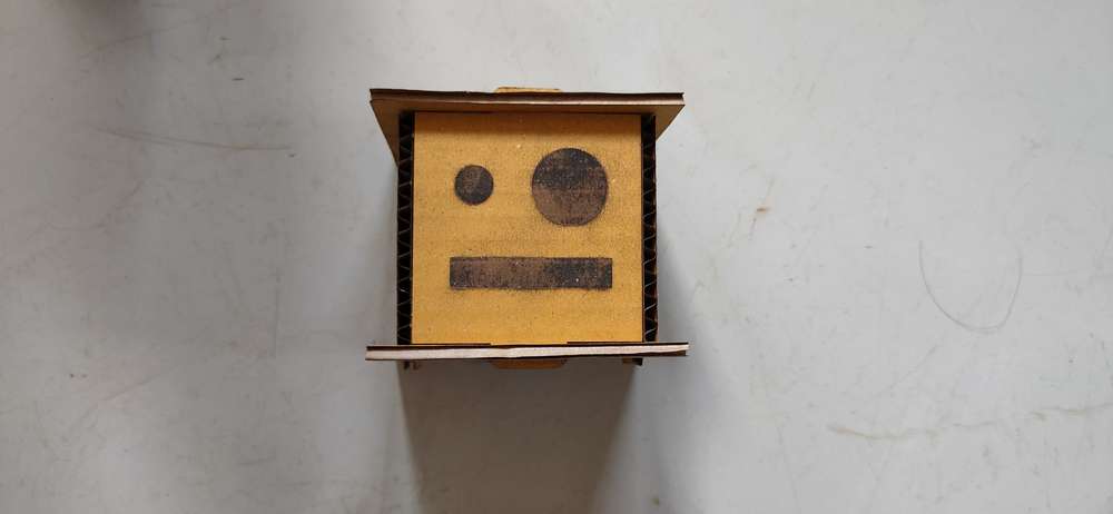
the construction kit
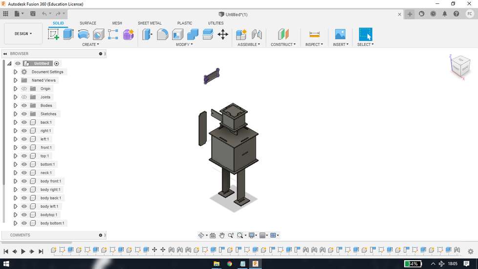
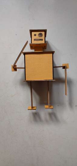
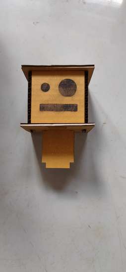
i designed a robot from fusion with the help of parametric
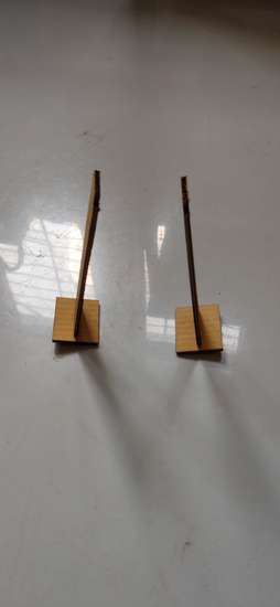
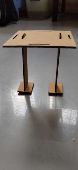
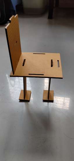
Results | Construction kit
here are the results
it didn't cut properly so i had to separate the pieceswith the help of cutter

here is the robot
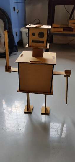
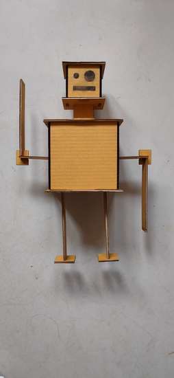
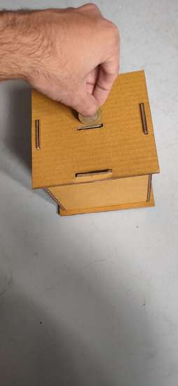
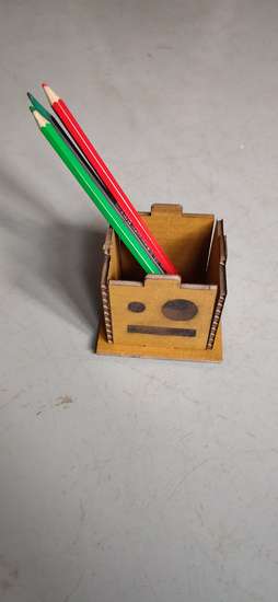
here is the assembly


puzzle pieces
castle
mr bean dots
robot parts
different press fit
Learning outcomes
Thsi week i learned how a leaser cutting machine works and how to operate them. I learned that to cut any material there are main two criteria: power and speed. If you are cutting material like cardboard, you need to set higher speed and low power and vice-a-versa for the materials like acrylic. I also learned about what is kerf and it's calculations, however i don't follow the kerf calculations method. I am more comfortable with directly cutting the piece first and then make the necessary changes according to the results i get . (i understand that kerf calculations is very important if the material i am cutting is very expensive and i can't do trials and error)
Drip Irritation by Fenil Chandarana is licensed under Attribution-NonCommercial-NoDerivatives 4.0 International![]()
![]()
![]()
![]()